milliSoC prototyping with ARM MPS3 platform
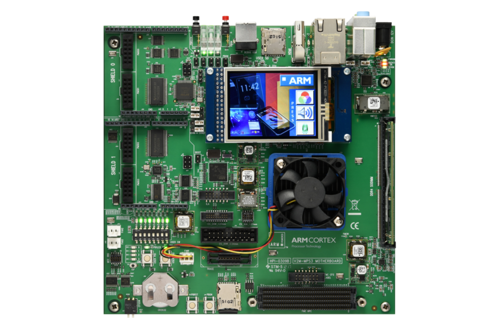
This example design flow supports the milliSoC reference design with the ARM MPS3 development board as a target. This FPGA prototyping environment has a larger Xilinx Kintex Ultrascale KU115 FPGA, plus plenty of peripherals including 4GB DDR4 memory, HDMI, and Colour display + touch screen.
The milliSoC reference design is aimed as a midrange SoC design space with a more capable SoC reference design that the entry level nanoSoC reference design and less complex than the Linux operating system capable A class megaSoC reference design.
The MPS3 FPGA development board uses a 'bare metal' FPGA and does not have the variety of hard IP cores of other boards like the Xilinx Pynq boards. This environment is suited to the SoC Labs reference design principle of avoid reliance on hard IP cores and the Processing System so that the SoC design can be fully instantiated in a synthesizable form within the MPS3 configurable resources to support their verification prior to ASIC tape out. The design instantiated in the FPGA fabric will be close to the Silicon chip fabricated after tape out, with no other dependencies. This environment has less built in prototyping support than Xilinx ZYNQ/PYNQ environment which allows quick prototype progress but defers the programming and verification of the full SoC design to later stages of the design flow. More of the programming and verification of the full SoC design is required earlier using this FPGA environment.
Connecting to MPS3
(also see getting started guide from Arm)
Connecting to the Arm MPS3 board is done using the USB debug Port. When connected to a host computer, it will appear as up to 4 COM ports, and a mass storage device. *if the mass storage device does not show up, start a terminal with the lowest COM port (this is the consol port) and type usb_on*
In the mass storage device you can download bit images into /MB/HBI0309B/***/***.bit
You must also include a ***.txt file that has the below information:
[FPGAS]
TOTALFPGAS: 1 ;Total Number of FPGAs
F0FILE: custom.bit ;FPGA0 Filename ← edit this filename
F0MODE: FPGA ;FPGA0 Programming Mode
And then edit the /MB/HBI0309B/board.txt file to point to your ***.txt file
[APPLICATION NOTE] ;Please select the required processor
APPFILE: CUSTOM\custom.txt ;My custom design ← edit this path
Once you eject the mass storage device you can press the ON button and the FPGA bit file will be loaded
milliSoC FPGA structure for SoC testing
(under development)
milliSoC FPGA build scripts
(under development)
milliSoC FPGA running and software
(under development)
Projects Using This Design Flow
Experts and Interested People
Members


Add new comment
To post a comment on this article, please log in to your account. New users can create an account.