


SoC Labs Accelerator Wrapper
In order for an accelerator to be integrated within a SoC, the accelerator needs to share interfaces with the system. The natural interface exposed by an accelerator engine may be different from that accepted by the broader SoC. In the case of the reference NanoSoC, an AHB-lite bus is utilised. A translation layer needs to be implemented - which has been called a 'wrapper'.
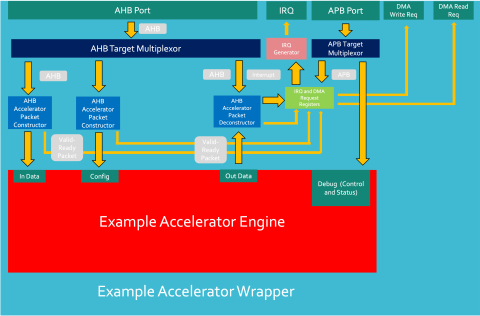
The NanoSoC wrapper has external AHB and APB interfaces and will instantiate the accelerator engine and packet constructors, de-constructers and buffers. Additional hardware such as wrapper configuration registers, control logic and interrupt generation may also be instantiated within the wrapper for more complex application-specific implementations of generalised accelerator engines.
The IP for the SoC Labs Accelerator wrapper is available here.
Basic Wrapper Overview
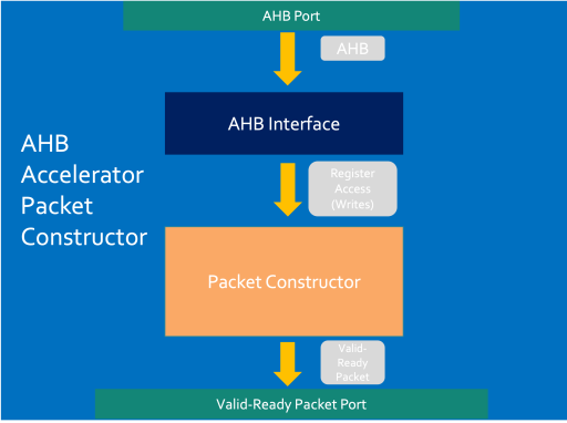
The diagram below shows the structure of an AHB Accelerator wrapper and how the components interact.
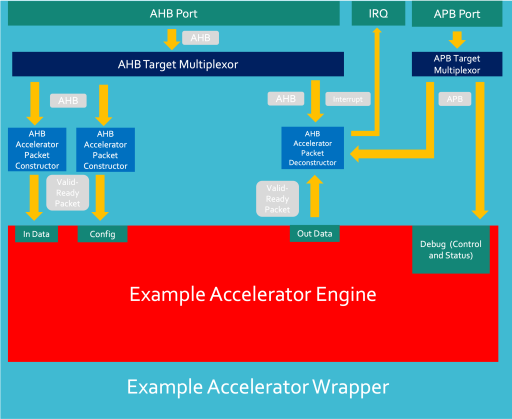
Input Data Transaction Flow:
- AHB Write comes from a System Initiator and enters AHB port - these signals are multiplexed to the correct target.
- Within each AHB Packet Constructor, an AHB interface converts AHB signals and creates register accesses.
- Register accesses address Accelerator Packet constructors which build packets from (multiple) write transactions and converts into Valid-Ready Handshake signal.
- Engine ports handshake with the Packet constructor and transfer data into the engine.
Output Data Transaction Flow
- Engine generates output data.
- Engine handshakes with Packet Deconstructor and packet is stored in packet deconstructor.
- Deconstructor raises interrupt to System Initiators.
- System Initiator creates AHB read to accelerator wrapper deconstructor address.
- Deconstructor breaks packet into multiple AHB data-width packets which are then sent back as AHB reads in the AHB data phase.
- Once all data is transferred out the interrupt is dropped.
Debug Transaction Flow
- Accelerator Debug registers are directly addressed mapped into accelerator wrapper.
- APB transactions are passed through wrapper directly into engine.
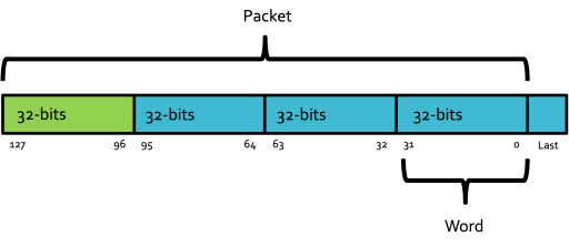
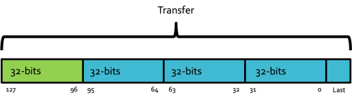
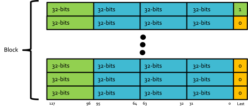
Data Transfer Sizes
Below show the different terminologies of data transfers in the wrapper:
Wrapper Usage considerations
Packet Constructors and Deconstructors are address mapped within the accelerator wrapper. A good first start is to think about the address space of your accelerator and how to divide it up. If suitable, making your address space as a multiple of 4KB is a good idea as 4KB is the page size for Arm Processors. It is important to keep note for both the wrapper design and for the system integration section.
Consider how many packet constructors and deconstructors are needed. Each Input/Output Channel will likely need its own Constructor/Destructor as per the example above. However, the engine configuration channel, if it is not expected to change very often, could be wired into wrapper registers and then modified over APB transactions instead of having to send a configuration packet for every data input block to be process in the engine. In the simple situation (above), there are two Packet Constructors and one Packet Destructor. The address space within the accelerator needs to be divided up.
The space division could be evenly split, it could be divided up such that the Input Addresses are equal to the output addresses - there is free rein with this this as long as there are enough addresses to address the width of the Packet Constructor/Deconstructor - this will be explained later on. It is advised not to have gaps within the accelerator address space however, and instead implement wrapping addresses - multiple addresses addressing the same physical address.
The current NanoSoC AHB interface splits the register accesses depending on their address to the correct Constructor/Deconstructor device. This may need to be modified to fit any application specific address space.
Packet Constructor Usage
The AHB packet constructor is comprised of 2 internal components - an AHB interface which converts AHB transactions to Register Accesses and a Packet Constructor which builds Valid-Ready Packets from multiple Register Accesses.
The packet constructor converts register accesses to Valid-Ready Packets which can be handshaked into the accelerator engine input ports. The packet constructor needs to be address mapped within the wrapper (as discussed above). Multiple 32-bit AHB writes are written to the Packet Constructor. The Packet constructor stores these writes if they are sequential write addresses until a write hits the last address in a line. Once an address ending in 0xXXXX_XXFC has been written, the packet will be valid and handshaked into the engine (or intermediary buffer).
If the last address written ends with 0xXXXX_X7FC (in the case where 2KB has been assigned to an input port and has a base address at 0xXXXX_X0000), a last flag is generated with the packet.
To use the constructor, an awareness of how many 32-bit words are to be sent is required to be able to pre-calculate the address to write to get the packet transfer on the correct AHB write.
To demonstrate this, the example below shows an accelerator with a 128-bit Valid-Ready Input Port and a 32-bit AHB interface.
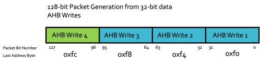
Only on the last write will the packet be transferred out (4th write in this example). Upon the last address being written, the packet is written out whether or not some or all of Writes 1-3 have taken place. If they haven't taken place, these 32-bit chunks of the packet will be set to 0.
Last Signal Generation
The Valid-Ready handshake can have a last signal associated with it so the accelerator knows when the last packet has been transferred into it. This last signal is generated only when a write occurs to the last word address in the Packet Constructors address space. In a 2KB address space, this would be an address ending in 0x7FC. The idea of this is to allow multiple packets to comprise a message block and for the accelerator to know which is the last packet of the block (so it knows when to start a new one).
Packet Deconstructor Usage
The AHB Packet deconstructor is made up of multiple components and has two jobs: Deconstruct Valid-ready packets into AHB transactions and to generate an interrupt when a new block of data is available to deconstruct.
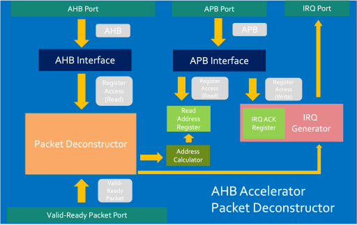
The operation of the deconstructor is relatively straight forward:
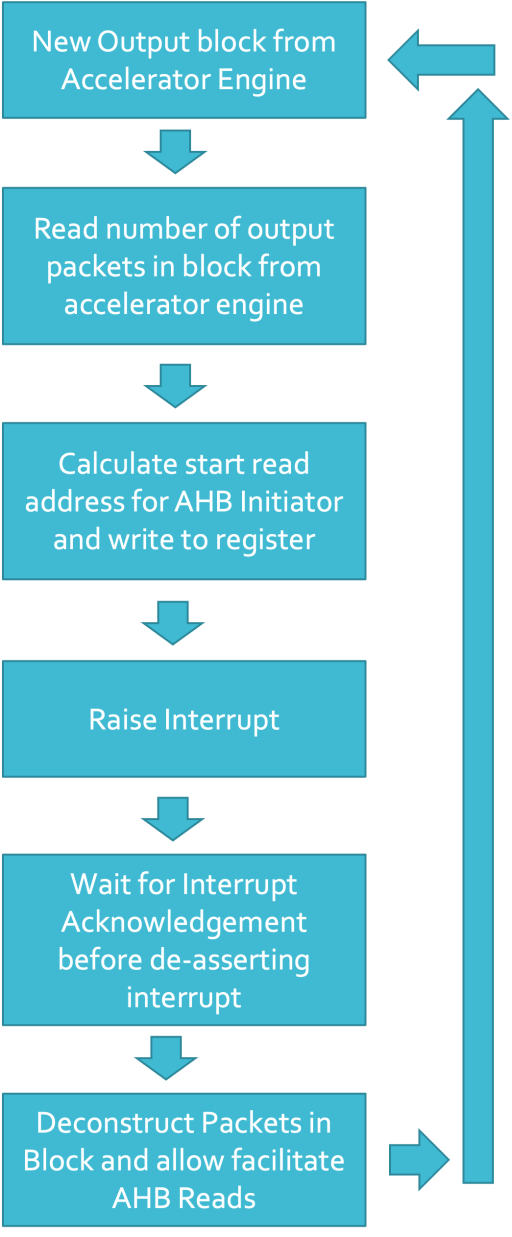
The packet deconstructor converts the Valid-Ready packets provided by the engine into 32-bit words which can then be transferred by AHB-reads. It works in the opposite way to that of the Packet Constructor. When the last 32-bit word of the packet has been read, the packet Deconstructor will raise its ready signal to retrieve another word from the engine.
The packet deconstructor raises an interrupt when it receives a new block of data. It writes the starting address for the initiator to read from (either from a side-band channel or from an internal register from within the accelerator) to a status register which the CPU can come and read. The CPU then writes to a acknowledgement register which de-asserts the interrupt and the CPU (or debug or sets up the DMA to) then read from the starting address through to the end of the packet deconstructors address region.


Add new comment
To post a comment on this article, please log in to your account. New users can create an account.