Continuous Integration and Deployment for verification
Continuous Integration and Deployment is a project development technique to merge code changes from a project team into a central repository where automated build and testing are used to find any system integration issues and provide versions of the project for continued development an fixes issues. Version control in the repository can provide either stable versions of the project or latest state of change.
Continuous Integration/Deployment (CI/CD) within SoC Labs is used to test a Project repository build for a SoC design by compiling and deploying a project on and FPGA and verifying the functionality. This is achieved using Git runners. A runner is a process that picks up jobs and executes them on a PC/server. Multiple runner machines can be used for larger scale projects or different deployment environments, or a single machine can used to automatically test a project it develops. The runners will execute a CI/CD pipeline every time a new commit is made to the repository or can be schedule to run periodically to make sure a SoC design project and development environment are stable.
Setup a CI/CD runner
Prerequisites:
- A PC/server with an environment setup with the required FPGA tools (e.g. Xilinx Vivado)
- Connected FPGA board (e.g. Xilinx ZCU104)
- Git account and project repository
This guide will run through how to make a group runner, and setup the CI/CD script. You can setup individual project runners, however a group runner can be more useful as you can have multiple projects within your git group using the same runner. This guide uses gitlab but similar steps can be used with github
- Install gitlab-runner
- Follow steps outlined here https://docs.gitlab.com/runner/install/ depending on your system
- For linux you can run:
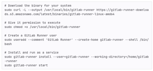
- Register your runner to your group
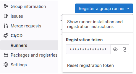
- In gitlab go to CI/CD -> Runners. There you can find a button for "Register a group runner"
- You can then register your runner on your machine using: sudo gitlab-runner register --url <your-group-url> --registration-token <your-registration-token>
- In your CI/CD -> Runners tab on your group git you should then be able to see your machine
- Add tags to your runner
- Tags are used to identify which runner should be used for different jobs. You can use any tags you want to, however we would suggest using tags that identify different environments. For example this could be different software, or different FPGA board that are connected. This becomes particularly important if you are using multiple runners with different environments.
Add your CI/CD pipeline
Once you have your git runner set up, you can now add a pipeline to your project to test your build and deployment. Each pipeline can be made up of many steps, for this example we will create a compile, build and deploy stage. However, for your SoC project this may also include simulation and synthesis.
- Go to your project repository
- Open CI/CD -> Editor and press Configure pipeline
- This will make a .gitlab-ci.yml file in the top of your git repository
- The default file is made up of 3 stages: build, test and deploy along with scripts for each stage which currently just prints messages but does nothing of use
- Under stages, remove the test stage. And add a comiile stage. You should now have compile, build and deploy
- Delete the scripts below to start from scratch
When a stage runs it will clone the latest repository into your gitlab-runner user area and run the script from the repository top directory
CI/CD Compile Stage
For this example we will be using the nanosoc_tech repository as an example. To be able to build and deploy onto FPGA, we have made a bootloader which is encoded in ROM. The first step therefore is to compile this bootloader and convert to a verilog file. A basic implementation is shown below:
compile-bootrom:
stage: compile
script:
- source ./set_env.sh
- mkdir -p $NANOSOC_TECH_DIR/system/src/bootrom
- make -C $NANOSOC_TECH_DIR/system bootrom SIM_TOP_DIR=$NANOSOC_TECH_DIR/sim BOOTROM_BUILD_DIR=$NANOSOC_TECH_DIR/system/src/bootrom TOOL_CHAIN=ds5
artifacts:
paths:
- ./sim/bootloader/bootloader.hex
- ./system/testcodes/bootloader/bootloader.hex
- ./system/src/bootrom/verilog/bootrom.v
- ./system/src/bootrom/bintxt/bootrom.bintxt
tags:
- ds5
Breaking down how this works in the CI/CD script, the first line is the job name, in this case "compile-bootrom". Next it tells to pipeline what stage this job relates to, in this case the compile stage. After this we have a simple bash script which sets the environment variables, makes a directory to store our verilog bootrom into, and then runs a make file which will compile the bootrom.
Each time a job runs it cleans the area where it clones the repository, this means it will get rid of any files generated in previous jobs. In order to keep these files you have to use the "artifacts" attribute. And by using "path" we can specify the path where the files are which we want to keep. For other types of artifacts refer here
Lastly we have the tags. This tag tells the job handler which runners can be used for which jobs. In this case we have specified "ds5", which refers to the arm ds5 tool chain used to make the bootrom file.
CI/CD Build Stage
This has scripts to build for both the Xilinx ZCU104 and Z2 boards. For these scripts to work you have to ensure you have your environment is setup correctly. Specifically you must have the relevent Arm IP and the $ARM_IP_LIBRARY environment variable pointing to the directory with the Arm IP in it. For the NanoSoC, you need the Cortex M0, Corstone-101 and PL230 IP downloaded and uncompressed.
build-job-ZCU104: # This job runs in the build stage
stage: build
script:
# move to fpga_imp directory and run the fpga build script for pynq z2
- cd ../../nanosoc_tech/system/fpga_imp/
- source ../../set_env.sh
- if source ./build_fpga_pynq_zcu104.scr; then echo "Vivado Finished"; fi
- FILE=./pynq_export/pz104/pynq/overlays/soclabs/design_1.bit
- if test -f "$FILE"; then
- echo "Build successful"
- else
- echo "Build failed"
- exit 1
- fi
artifacts:
paths:
# Keep the generated bit and hwh file from fpga build script
- ./system/fpga_imp/pynq_export/pz104/pynq/overlays/soclabs/design_1.bit
- ./system/fpga_imp/pynq_export/pz104/pynq/overlays/soclabs/design_1.hwh
tags:
- Vivado2021.1
Breaking down how this build script works. Firstly we have the job ID "build-job-ZCU104" and the stage name "build" which tells the job handler that this should run in the build stage. For the script we first move into the ./system/fpga_imp directory. This directory contains scripts to build a bit file for different FPGA boards, in this example we are looking at the Xilinx ZCU104. Next we have the runner execute the build_fpga_pynq_zcu104.scr script. This will automatically build an FPGA implementation of the nanosoc. More info on these scripts can be found here. Once the build script is finished it then runs a test to check if the "design_1.bit" file exists. If this exists then we know that the build script has built successfully.
Lastly we again have some artifacts that we need to keep for the deploy stage. Namely, these are the design_1.bit and design_1.hwh files. The tag we have used here is "Vivado2021.1" and this job will run on any runner that is set up with a Vivado 2021.1 installation.
CI/CD Deploy Stage
The deployment onto FPGA will be highly dependent on your system setup. Here we are using a VLAB environment courtesy of the University of York (details here). This is setup to be a multiuser server with multiple FPGA boards attached to it. The user can securely connect to a board through an ssh tunnel.
deploy-job-ZCU104: # This job runs in the deploy stage.
stage: deploy # It only runs when *both* jobs in the test stage complete successfully.
environment: production
script:
- echo "Deploying application to ZCU104"
- screen -dmS zynq -L -Logfile screenlog
- sleep 5
# copy over vlab.py and vkey and then connect to ZCU104 board
- screen -r zynq -X stuff "cp -r /home/dwn1c21/FPGA/. ./ \n"
- screen -r zynq -X stuff "./ZCU104_connect.sh\n"
- sleep 10
# use scp to copy over bit files and python script
- screen -r zynq -X stuff "scp -i ~/.ssh/id_rsa dwn1c21@soclabs.soton.ac.uk:~/builds/wzndG1mA/0/soclabs/nanosoc_tech/system/fpga_imp/CI_verification/load_bitfile.py ./ \n"
- sleep 2
- screen -r zynq -X stuff "scp -i ~/.ssh/id_rsa dwn1c21@soclabs.soton.ac.uk:~/builds/wzndG1mA/0/soclabs/nanosoc_tech/system/fpga_imp/pynq_export/pz104/pynq/overlays/soclabs/design_1.bit ./pynq/overlays/soclabs/design_1.bit \n"
- sleep 2
- screen -r zynq -X stuff "scp -i ~/.ssh/id_rsa dwn1c21@soclabs.soton.ac.uk:~/builds/wzndG1mA/0/soclabs/nanosoc_tech/system/fpga_imp/pynq_export/pz104/pynq/overlays/soclabs/design_1.hwh ./pynq/overlays/soclabs/design_1.hwh \n"
- sleep 2
# Need root access to load the overlay onto the FPGA
- screen -r zynq -X stuff "sudo su\n"
- sleep 1
- screen -r zynq -X stuff "xilinx\n"
- screen -r zynq -X stuff "source /etc/profile.d/pynq_venv.sh \n"
- screen -r zynq -X stuff "source /etc/profile.d/xrt_setup.sh \n"
- screen -r zynq -X stuff "source /etc/profile.d/boardname.sh \n"
- sleep 5
# run load_bitfile: this loads the overlay and checks that it has been loaded
# script will output "Overlay Loaded" if successful
- screen -r zynq -X stuff "python3 load_bitfile.py \n"
- sleep 40
# deactivate the pynq virtual environment and exit root access
- screen -r zynq -X stuff "deactivate \n"
- screen -r zynq -X stuff "exit \n"
# test the screenlog for "Overlay Loaded"
- cp ./system/fpga_imp/CI_verification/test_bitfile_ZCU104.sh ./
- chmod +x test_bitfile_ZCU104.sh
- ./test_bitfile_ZCU104.sh
after_script:
# cleanup xilinx directories and quit screen
- screen -r zynq -X stuff "rm load_bitfile.py \n"
- screen -X -S zynq quit
tags:
- ZCU104
The first thing this script does is open a detached screen. This is done so you can run the ssh tunnel on the detached terminal and continue running this script on your main terminal. If you did not use this method, when you connect to the FPGA board, the main script will hang and never complete. We then copy over the files needed to connect to the VLAB and run the ZCU104_connect script which opens up the connection to the board.
Now the detached screen is running in the FPGA environment we can copy over the .bit and .hwh files using the scp command. This is setup to use ssh-keys so that no passwords need to be shared in your CI/CD environment. We also copy over a load_bitfile.py file. This file will run in the pynq environment and load the bitfile overlay. We then source some environment scripts: pynq_venv.sh, xrt_setup.sh, and boardname.sh. These are used to start the pynq virtual environment on the ZCU board. To do this we also need to be root and so use sudo su to get root access.
Now the setup is complete and we have all the necessary files in place we can run the load_bitfile.py script which will load the bitfile and then output "Overlay Loaded" when it is finished. Once finished we then deactivate the pynq virtual environment and exit root access.
Lastly we need to check if the bit file has actually been loaded. When we first opened the detached screen we made a log file called screenlog. We then copy the test_bitfile_ZCU104.sh script into our current directory and run it. This script compares the output of our screenlog file to what we should expect the output to be. If the output doesn't match what we expect it exits with code 1 which will indicate to the CI/CD that the deploy step has failed.\
In this deploy example we have an afterscript which cleans up the working environment. This first deleted the load_bitfile.py file from the ZCU board, and then closed our detached screen.
Conclusion
Here we have shown an example of how you could implement some automated CI/CD testing of your project repository. This contains the basic functionality to compile your bootloader, build your FPGA bit files, deploy to your FPGA board and run some tests on your SoC implementation. Further extensions can be made to this process including adding a simulation step that can run some test vectors on your simulated SoC, as well as adding more test functions to your FPGA deployment to run test vectors on your implemented SoC.
Projects Using This Design Flow


Experts and Interested People
Members


Related Project Milestones
| Project | Name | Target Date | Completed Date | Description |
|---|---|---|---|---|
| Battery Management System-on-chip (BMSoC) for large scale battery energy storage | Continuous Integration and Deployment for verification |
Analog Design
|
||
| Check year | Continuous Integration and Deployment for verification (177) |
Add new comment
To post a comment on this article, please log in to your account. New users can create an account.