Behavioural Modelling
Introduction
This stage of the hardware design task creates one or more "Behavioural Model" of the system based on the architectural blocks defined the previous stage of the design flow. There are a variety of methods to undertake modelling activities in any System on Chip design task.
If there is a very clear and precise specification for a project then a formal approach to design refinement my be efficient. Projects can use formal methods to specify models and use formal model checking as the verification of the design.
If the definition of the system is less clear a more iterative approach to creation and testing of models may be more effective. Here the term design space exploration is often used where designers iteratively prepare models and use simulation based testing to examine the operational characteristics of alternative options in their design. Projects may develop executable software models of key system behaviour, critical algorithms or machine learnt models.
Some projects use visual methods of representing models to describe the system behavior, this can be helpful on larger projects to help communication and share understanding among a team. These help engineers convey complex ideas without encoding all the details needed by other methods.
Model Representation
Models can be developed in a variety of description languages and are not bound to hardware description languages so for example languages like MATLAB and Python can be chosen to build models in the early stages of design.
In a software/hardware co-design approach the model may be represented in a software language such as C++ this is then translated by High Level Synthesis into an RTL based hardware description. An RTL description might be translated into a C++ representation to run as part of a simulation for verification. Usually the representation taken forward to the next stages of the hardware development process is an RTL description.
In the digital domain Transaction-Level Modelling (TLM) can create a behavioural description of a system with enough detail to allow verification of the design by simulation.
Behavioural models for the analogue domain use forms of mathematical approximation, linear or non-linear regression, neural networks, etc. to define relations between inputs and outputs.
Behavioural Modelling within a System on Chip design context
Within SoC Labs the aim is to provide significant parts of the System on Chip as pre-verified IP and design patterns. The hope is this enables efficient co-design of the unique custom IP for the academic project need within an existing efficient system architecture. The unique IP could range from domain-specific compute accelerators to designs that provide real world monitoring / actuation or system security capabilities. These custom blocks can be modelled and developed independently and then integrated into one of a number of different SoC reference designs each with different operational characteristics.
Part of any engineering or hardware design task is developing a solution within some externally imposed envelope of constraints within which the overall system has to operate. The SoC Labs reference designs and design patterns help the project develop hardware blocks within a known view of a deliverable target system platform.
The aim of SOC Labs is simplify the integration of the RTL description of the custom hardware into the RTL description of the full SoC reference design for the full SoC that can be taken to physical fabrication and beyond that exercised as a system with an operational software system to exercise the custom hardware with real world workloads and obtain real world measurement of system performance. Creating an executable Behavioural model of the custom hardware allows for a software/hardware co-design approach where the eventual operational software can be developed in parallel and also become part of the verification assets for the custom hardware at various stages of the hardware design task.
Behavioural Design Decomposition
In any system design task, the prior phase of Architectural Design is further decomposed into behavioural design models and patterns. Parts of the system may be worked on in isolation by separate individuals or teams with each behavioural block having a verification process performed on it before integrating into a complete System on Chip. This means the Behavioural Modelling task may be iterated through a number of times, each pass through adding to the overall system design and verification assets.
Behavioural Design Patterns
Design patterns have been defined for many ways engineers commonly develop solutions to design challenges. Behavioral design patterns aid the design decomposition process, often dealing with the interactions between the various parts of the overall system. Engineers often get confused between the intellectual process of design decomposition and the tool they currently have in their hand. You will see statements such as 'written this way' or 'instantiated in this type of object'. Well conceived design patterns are ambiguous to implementation choices or tool chains. The Transaction Level Modelling (TLM) mentioned above is not a new approach to design just a refinement of the principle of 'separation of concerns', etc. It focuses on the interactions between parts of the system while allowing the implementation of the parts to be deferred to another design task.
Examples of Behavioural Design Patterns
Below is not an exhaustive list but are illustrative to get the reader to consider using existing design patterns rather than trying to do what has been done many times yet again from scratch.
Chain of Responsibility
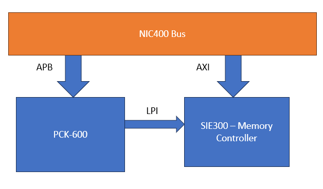
In this design pattern the interaction between the various parts of the system consist of passing the communication along a chain of the parts. Each part can independently decide to take action and/or to pass it to the next in the chain for their action. It can be used to implement actions within the system that need to be performed sequentially. One example is at system bring up where it is important that one part of the system is in a known state before other parts that depend on it start to use it. The 'system reset' communication can be passed along the Chain of Responsibility ensuring that parts that need to have their state established before others are placed before each other in the chain. This pattern was recently discussed for use by the SoC Labs team looking to implement a Memory Controller for DDR4 memory.
Behavioural Design for Machine Learning / Artificial Intelligence
Model development
There are a lot of software frameworks that provide for model development, model optimization and deployment. Details of these are not replicated here but within the SoC Labs there is an interest sections dedicated to the Machine Learning topic which aims to describe in more detail how SoC Labs implementations benefit from and interact with such model development frameworks.
Model development for ML/AI has tended to be a separated software/hardware co-design task. Usually models are developed in software, often in Python, using significant compute resources. The driver for model improvement is more often to increase accuracy with resource consumption a lesser aspect. A separate task then looks to optimse the model towards deployment with more resource constrained while minimising accuracy loss. Benchmarking is viewed as an acceptable gain in some system characteristic, energy, latency, etc. against some nominal loss in accuracy.
With diligent engineering it is possible to improve system characteristics without model accuracy loss. It should be remembered that the accuracy benchmark has been computed on a software platform that by its nature also has limitations. There is nothing to suggest a custom hardware solution should not outperform a classic CPU compute resource in terms of accuracy.
SoC Integration
You will find a number of SoC Labs projects have developed specialist models that are aimed at efficient inference using custom hardware accelerators that are integrated into the different SoC reference designs depending on the various demands of the application and model.
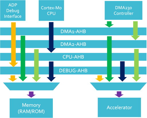
- nanoSoC reference design
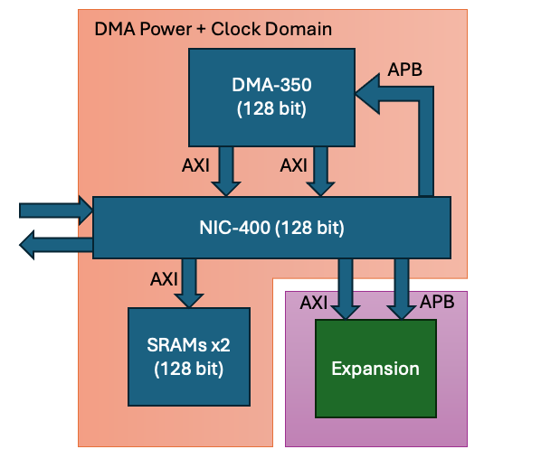
The nanoSoC can be extended for small ML/AI workloads. nanoSoC integrates the accelerator accelerator for the ML/AI workload via the AHB-Lite Bus Matrix configured from the corstone 101 base system architecture. Either the SoC processor, the Cortex M0, or the DMA controller (the AHB bus initiators) can marshal data into and out of the accelerator to/from memory. Depending on the internal data widths to be processed by the accelerator, a intermediate layer of logic, called a wrapper in SoC Labs projects, may be needed to translate between the 32 bit AHB packets coming from the bus to internal packets feeding into the core accelerator logic.
Projects Using This Design Flow

Experts and Interested People
Members


Related Project Milestones
| Project | Name | Target Date | Completed Date | Description |
|---|---|---|---|---|
| Battery Management System-on-chip (BMSoC) for large scale battery energy storage | Behavioural Modelling |
|
||
| Arrhythmia Analysis Accelerator : A-Cube | Behavioural Modelling (100) |
Implement an atrial fibrillation detection model in the ZCU104 FPGA board. |
||
| Arrhythmia Analysis Accelerator : A-Cube | Behavioural Modelling (100) |
Simulate (RTL) the selected atrial fibrillation detection core. |
||
| IMPLEMENTATION OF FIXED TIME BASED TRAFFIC LIGTH SYSTEM USING FPGA WITH VERILOG HDL. | Behavioural Modelling |
abstract representation of the system |
||
| ADC Integration in nanoSoC | Behavioural Modelling |
Model the analog behaviour of the subsystem and confirm it meets the requirements |
Add new comment
To post a comment on this article, please log in to your account. New users can create an account.