A digital audio dynamic range compression accelerator for mixed-signal SoC
Compression Overview
The dynamic range processor is a DSP function which does as it says on the tin; it compresses the dynamic range of the incoming signal. This is used most commonly in the music industry for its effects on the perceived loudness of audio. It is also used extensively in hearing aids to compensate for the user’s reduced dynamic range of hearing. In this project a hardware accelerator is developed for the purpose of dynamic range compression of digital audio. This accelerator will be implemented in a mixed-signal infrastructure.
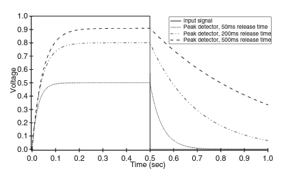
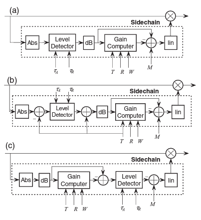
The compressor has several key components, the first of which is the level or peak detector. The purpose of this component is to produce a smoothed representation of the audio signal according to specific attack and release time parameters. The attack time parameter determines how long the peak detector takes to respond to, and reduce the gain of, a peak in the input signal. For hearing aid applications, this value is very small and has a typical value of < 5ms as the device must be capable of responding to loud sounds quickly so as to not damage the user’s ears. The Release time determines how long it takes for the level detector to respond to a minimum in the input signal and stop reducing its gain. The Placement of this level detector within the compressor is important as it determines the dynamic range of the signal which is to be smoothed. This will become more apparent later on.
The gain computer is the next key component. This block produces what is called the control signal; the signal that modulates the original audio input signal. This is computed by comparing the level of the incoming signal with a pre-stated threshold value, T. If the incoming signal has a level greater than the threshold value, the signal’s gain will be reduced by a factor of R, the ratio parameter, until the input signal’s level returns to below the threshold. The third parameter of the gain computer is the knee-width, W, this value controls the smoothness of the transition between non-compression and compression by curving the compression profile as seen in figure 2. The final parameter is the make-up gain, M, this is used to increase the total gain of the output signal. The input of the gain computer is subtracted from the output of the gain computer to produce the control signal. These parameters and their effects are detailed in figure 2.
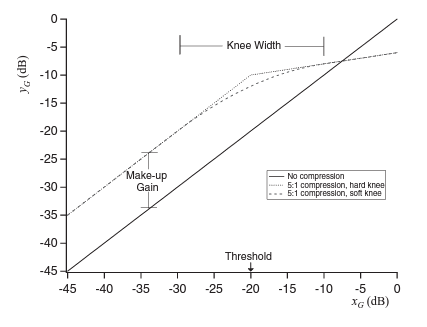
The parameters T, R, W and M are all conventionally in decibels due to the nonlinear nature of audio signals, therefore it is beneficial to perform the gain computer calculations in the logarithmic domain.
The design of this accelerator will follow the accelerator design flow specified here.
Accelerator Specification
The first stage is the specification of the accelerator. In this stage research was conducted into what a compressor was and what different types existed. From this, I chose to implement a feedforward compressor as this seemed to be the most common variety. There was consideration of the resources that would be required from the accelerator and concrete definitions of what the input and output was expected to be. The input to the compressor will be 24-bit, 2’s complement, fixed-point, -1 to +1 samples from the audio codec on board the Pynq-Z2 FPGA developer board. The compressor will also operate in stereo which implies that two channels will be processed simultaneously.
Algorithmic Modelling
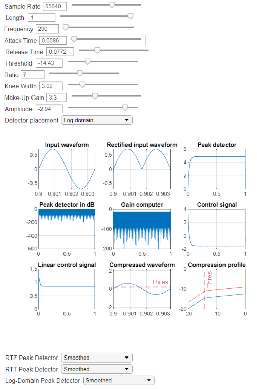
In the algorithmic modelling stage MATLAB was used to model several configurations and variable parameter values in-order to observe the behaviour of the mathematical model of the device and to decide upon what would actually be implemented in hardware. Figure 3 displays the application that was developed for this purpose. As you can see, the variables relating to both the compressor (Attack time, Release time, Threshold, Ratio, Knee width and Make-up gain) and the input signal (Sample rate, Length, Frequency and Amplitude) these may all be varied such that the behaviour of the compressor can be observed through the different signal chain observation points. Input waveform, rectified input waveform, compressed waveform and compression profile are fairly self explanatory or have been explained previously in this document, however explanation is required for the peak detector, control and gain computer waveforms. The peak detector and peak detector in dB waveforms are both measured at the point after the level detector block in figure 4. The control signals are measured after the linear blocks in figure 4. Finally, the gain computer signal is measured after the gain computer blocks.
Behavioural Modelling
Currently I am working on the behavioural modelling stage. So far, MATLAB’s HDL coder app is being used to aid the standalone development of SystemVerilog for the compressor. The blocks Abs and dB from figure 4 (c) have been implemented in HDL. Throughout the modules so far, a fixed-point, two’s complement binary system is being adopted to represent all numbers.
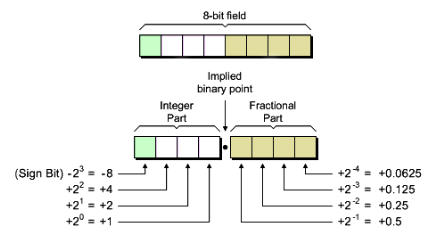
This involved defining a data type for FP numbers which contains the fractional and integer parts of the values. It is not currently known what the precision will need to be for the integral and fractional parts as in the different stages of the signal chain the number system changes from logarithmic to linear. The logarithmic values will determine the precision for the integral part as the input linear values will range from -1 to 1, therefore only 1 bit will be necessary to represent this. The fractional part will be determined by the precision required in both the linear & logarithmic numbers.
To expand on the implementation of the ‘dB’ block, a logarithm computation is commonly achieved with a look up table which has values for the specific range of the logarithm which will be used and the precision which the output requires. In this case, I have also considered the use of a Taylor series approximation to the base-10 logarithm which is required by the dB block in figure 4. This approximation is derived from a simple logarithm arithmetic rule and the Taylor series approximation of the natural logarithm,
log(x) =ln(x)/ln(10)
where,
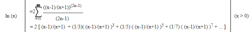
This function highlighted in green is the graph produced by this approximation, and blue is the base-10 logarithm. Of course, a lookup table would be exact but will make rounding errors and these may be significant if the precision of the LUT is not selected correctly. Higher terms may also be used in the Taylor expansion approximation but the benefits of this are outweighed by the computational resources required to compute terms of order higher than 7.
Project Milestones
Do you want to view information on how to complete the work stage ""
or update the work stage for this project?
-
Behavioural Design
Target DateThis stage should yield an HDL implementation of the design which was modelled in the algorithmic modelling stage. A completed accelerator core should be finished by this date.
-
System Integration
Target DateThis stage will produce the integrated system which may consist of the finished Hardware-described accelerator integrated with a wrapper to interface with the AHB bus architecture that the Mixed-Signal SoC is likely to use. Specification of the exact SoC will be available closer to the time but the general idea is that it will be based on the NanoSoC architecture.
 Peter Richards
Intern
at University of Southampton
Research area: Digital Signal Processing
![]() Accelerators
Accelerators
![]() Hardware design
Hardware design
![]() Accelerator Design Flow
Accelerator Design Flow
Submitted on
Add new comment
To post a comment on this article, please log in to your account. New users can create an account.