Wireless smart machine box for industrial IoT fault detection and notification
The frequent collisions and vibrations means each machinery component in modern factories usually suffers from worn out and aging, which destroys the system and outputs invalid results. When machinery fails, it increases costs for producers and affects the quality of factory production. Therefore, the industry gradually values the predictive maintenance (PdM) system.
Among different rotating machinery, bearings and gears play a significant role. Bearings can not only fix the shaft in the center position but also reduce the friction loss between the shaft rod, which increases the rotation efficiency. In addition, gears are used to change the rotation speed and generate huge torque to drive more complex mechanical components through the transmission of gears with other toothed mechanical parts. In terms of traditional mechanical fault diagnosis, the type of fault is determined by applying complex signal processing mechanisms to analyze the collected vibration signals. However, this method's time and labor costs are considerable because sophisticated experts are required to perform this kind of signal-processing-based methods. For medium-sized enterprises, the high time and labor costs become huge cost burden.
Because of the abovementioned reasons, this work had developed a wireless smart machine box for industrial IoT fault detection and notification, which features:
- Support fault diagnosis to multiple types of machinery simultaneously: We first use an artificial intelligence technique to simplify a complex diagnosis process. Besides, this work can distinguish the sensing data from different machineries to extract the corresponding data features automatically. In this way, the work can support the fault diagnosis to multiple machineries without any prior knowledge, thereby reducing the diagnosis cost.
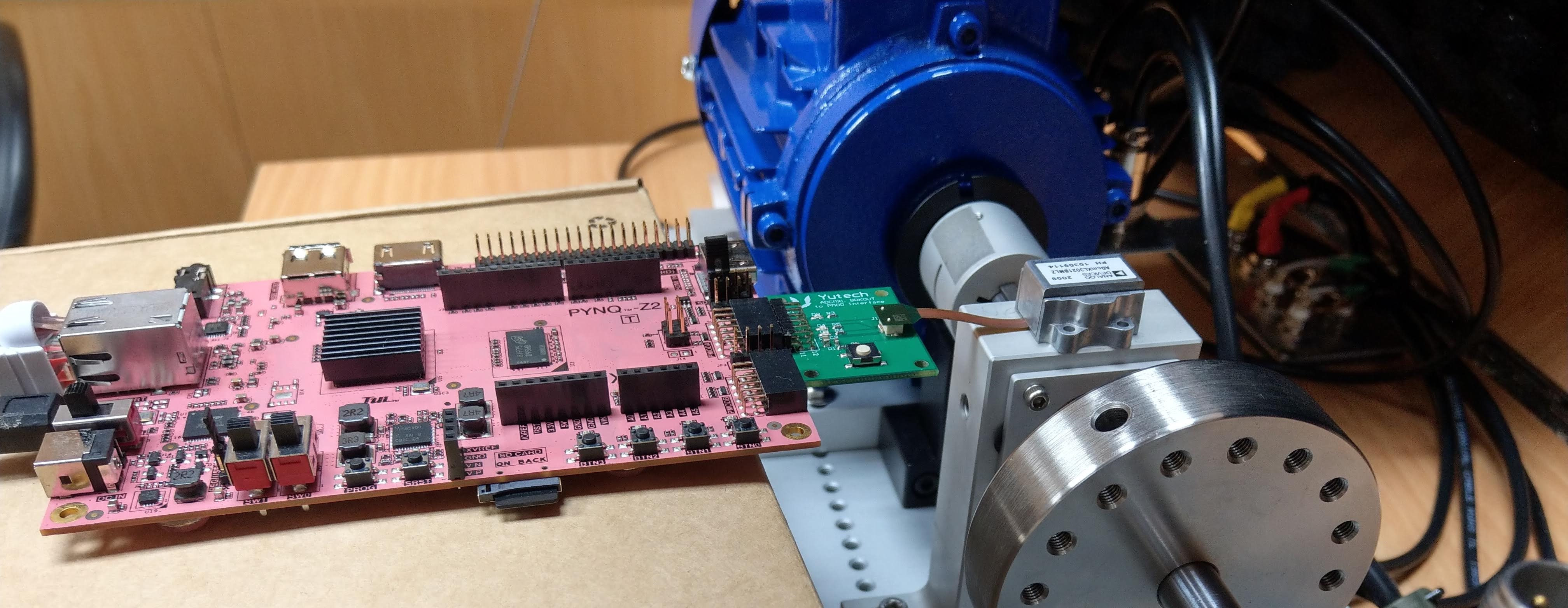
- Support wireless sensing diagnosis technology: This work uses Xilinx Pynq FPGA to develop the diagnosis platform used to perform the machine learning diagnosis operation module. Besides, this work integrates the ADI Voyager wireless CbM sensor receiver module and Xilinx Pynq FPGA. Therefore, this work can process the received sensing signal and perform the diagnosis in real time.
- Support real-time fault diagnosis notification in an IIoT environment: In addition to integrating the ADI Voyager wireless CbM sensor receiver module, this work also integrate the wireless transceiver module with Xilinx Pynq FPGA, which is used to upload the sensing signals to the cloud database. When the fault is detected, the diagnosis results will be notified to the mechanical maintainer via email.
Through the technology developed in this work, mechanical maintenance personnel can grasp the current operating status of the machinery in real-time and use the received fault diagnosis results to quickly carry out repairs and maintenance.
Fig. 1 shows the software-hardware collaboration architecture of the work. The ADI Voyager wireless CbM sensor is first deployed in multiple motors to collect the operating vibration signals of each motor. Afterward, the ADI Dust Network is employed to perform anti-noise data transmission. The Dust Network uses the 2.4GHz frequency band, and can establish a SmartMesh with different ADI Voyager wireless CbM sensors. In other words, each wireless sensor can not only be used to sense vibration information but also be used to assist in transmission from other wireless sensors. In this way, it can achieve a more than 99.999% transmission reliability in a very harsh transmission environment and achieve accurate remote sensing requirements.
When the ADI Voyager wireless CbM sensor receiving module integrated in Xilinx Pynq FPGA receives the signal, this work uses Direct Memory Access (DMA) technology to quickly capture the sensing data to ARM for further data pre-processing and the feature extraction. Afterwards, the developed light random forest model is used to perform fault diagnosis. Meanwhile, this work also uploads the sensing time domain signal, sensing frequency domain signal, and waveform file to the cloud database through 802.11n wireless network technology (i.e., this work uses Google Drive as the example). In this way, mechanical maintenance personnel can check the current mechanical operation status in real-time and carry out maintenance in advance. On the other hand, once the faults are detected, the fault diagnosis results, including fault time, fault type, fault waveform, and the cloud database link, will be sent to the maintenance personnel's email through the SMTP suite of Xilinx Pynq FPGA to achieve the goal of real-time notification.
The proposed wireless smart machine box for industrial IoT fault detection and notification can help enterprises diagnose and monitor the health status of multiple machines simultaneously with lower maintenance costs. Therefore, this work can greatly reduce the enterprise’s cost burden for machinery maintenance.
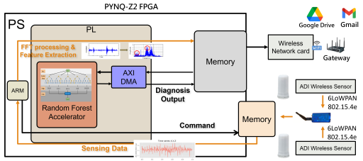
Fig.1 Architecture diagram of fault detection platform applied to multi-component vibration data.
Project Milestones
Do you want to view information on how to complete the work stage ""
or update the work stage for this project?
-
Milestone #1
Target Date -
Milestone #2
Target Date -
Milestone #3
Target Date -
Milestone #4
Target Date -
Milestone #5
Target DateIntegrate FPGA and ADI wireless vibration sensors.
-
Milestone #6
Target DateComplete to communicate with multiple wireless vibration sensors and do multiple fault diagnosis simulteneously
Team

 Kun-Chih (Jimmy) Chen
Associate Professor
at National Yang Ming Chiao Tung University
Research area: Multiprocessor SoC (MPSoC) design, Neural network learning algorithm design, Reliable system design, VLSI/CAD design, Smart manufacturing
ORCID Profile
![]() Machine Learning
Machine Learning
![]() Hardware design
Hardware design
Submitted on
Comments
Latest state of the project
Hi,
It would be great if we could post here the latest state of the project?
John.
Yes, you can. We are going…
Yes, you can. We are going to create a new topic for SoC Lab 2024. I will let you know when I am done.
Jimmy
Moving beyond FPGA implementation
In order to move the design beyond an FPGA implementation and towards an ASIC the parts that are dependent on the FPGA fabric will need to be become part of the design so they can be fabricated. We are looking at the AAA IP parts needed for an AXI interconnect design.
Use of DMA and AXI
Hi,
Can you expand a little on your implementation of AXI and Direct Memory Access (DMA) technology to capture the sensing data to the ARM processor for further data pre-processing and the feature extraction? Which parts are you depending on in the Xilinx Pynq FPGA and which are you picking up from the AAA?
John.
[Reply] Use of DMA and AXI
To start, we plug the ADI vibration sensor's wireless receiver into the USB port of the Xilinx Pynq FPGA. This allows us to receive wireless vibration sensing data. Next, we use the AXI Serial Peripheral Interface (SPI) to capture the sensing data and execute a Jupyter notebook on the ARM processor for control. This connection also enables us to access data via the Direct Memory Access (DMA) controller in the programmable logic (PL). Within the Xilinx Pynq FPGA, we establish various IPs, such as AXI GPIO, AXI Quad SPI, Concat Interrupts, and AXI DMA. With the help of AXI Interconnection and Clocking Wizard, communication is achieved between the AXI DMA and processing system (PS), as well as between the AXI Quad SPI and PS.
Regarding the AAA, I thought we should click it while submitting the project because the involved Xilinx Pynq FPGA contains an ARM processor. It should be a mis-clicking.
Add new comment
To post a comment on this article, please log in to your account. New users can create an account.