Firmware
The definition of firmware varies but most describe a specialist form of software that is by design tightly coupled to hardware behaviour and intrinsically linked to the operation of the hardware. In some systems the definition can be simplified by where it is physically stored or how it is executed by a processor. Development of firmware may require assembly programming (an understanding of the Arm instruction set). As a System on Chip design becomes more complex these simpler definitions are no longer valid as firmware can be compiled from other languages, loaded from any addressable memory, etc. Firmware must usually operate within tight constraints of the hardware and have to perform its operation without error and in specific time periods. Unlike application software, which in general is designed to operate in isolation from hardware concerns, firmware acts on the physical hardware operation for example changing critical system register values. A firmware engineer must have in depth understanding of the hardware operation and behaviour.
Design Patterns
Design patters are helpful to structure software, they represent reusable design experience, simplify and speed-up the design process, reduce the risk of errors, improve testability and allow communication between designers.
The 'Endless Loop' or 'Super Loop' design pattern.
This design pattern is often the core pattern of a bare metal embedded system. After initialising the system it runs a single loop that iterates indefinitely. In an embedded system, critical tasks need to be executed within specific time constraints. The infinite loop repeatedly performs the predetermined sequences of tasks needed to operate the system. For example reading sensor data and then actioning some actuator.
void main (void)
{
 // initialisation

   while (1) { // "endless/super main loop"
   // do work
   }
}
The tasks assigned specific time intervals within the loop and this simple pattern avoids complex scheduling and task switching making efficient use of the limited system resources. It easy to understand, develop and debug. It does require the designer to be explicit in task priorities and timing requirements to ensure system behaviour. The downsides also result in a polling based design that can waste resources and in large systems the loop can become complex and hard to maintain.
To improve the system design, the basic infinite loop architecture pattern is enhanced with an event driven design pattern and uses interrupt-driven programming methods for time critical actions that can be executed in priority order. If there are no tasks to execute the processor can save resources by being put into a sleep state.
void handle_event ()
{
 // do stuff
}

void main (void)
{
 // initialisation

   while (1) { // "endless/super main loop"

	if (event)
	{
	  handle_event ();
	}
	else
	{
         sleep();
	}
   }
}
The Arm Cortex-M0 supports a sleep mode and a deep sleep mode. More complex designs can also implement additional sleep modes using design specific programmable registers.
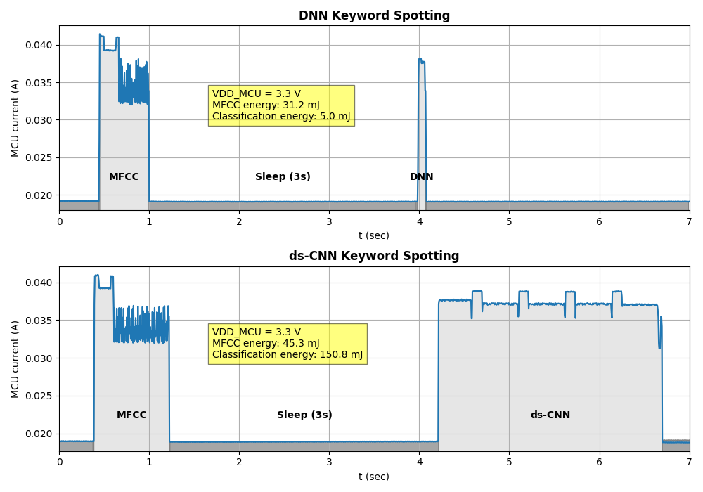
The Cortex M0 sleep mode stops the processor clock. The deep sleep mode, stops the system clock and can power off additional functions such as any PLL or memory subsytem. The processor also supports, Sleep-on-Exit, where the processor enters sleep mode after all exception handlers in the event based system have been executed. Defining hardware power domains within a SoC design and controlling their activation via additional programmable registers and custom sleep states can reduce system power consumption or in the case of academic systems enable fine grained energy measure of parts of a research system for description of experimental results for academic papers.
The main loop in the CMSIS-Core (Cortex-M) software is instantiated in this design pattern.
// The processor clock is initialized by CMSIS startup + system file
void main (void) {                               // user application starts here
  Device_Initialization ();                      // Configure & Initialize MCU
  while (1)  {                                   // Endless Loop (the Super-Loop)
    __disable_irq ();                            // Disable all interrupts
    Get_InputValues ();                          // Read Values
    __enable_irq ();                             // Enable all interrupts
    Calculation_Response ();                     // Calculate Results
    Output_Response ();                          // Output Results
    WaitForTick ();                              // Synchronize to SysTick Timer
  }
}
Handling interrupts
In bare-metal firmware Interrupt handlers are the essential building block of the system. Interrupt handlers manage the time-sensitive events. They are used to implement the event driven design pattern and use of the microcontroller’s interrupt architecture to configure and prioritize interrupts to determine the system software flow to optimise resource use effectively. Interrupt handlers respond to specific events (interruptions) that are either generated by parts of the SoC external to the processor or by the firmware running in the processor.
External interrupts come in via interrupt lines which that are usually routed to SoC specific peripherals such as Direct Memory Access (DMA) engines, General Purpose Input/Output Pins (GPIOs), etc. All of these interrupts are configured via a peripheral known as the Nested Vectored Interrupt Controller (NVIC). The Arm M0 processor implements the Nested Vectored Interrupt Controller
The CMSDK for M0 the Device Startup File defines the initial contents of vector table including the start addresses ("exception vectors") for all exception handlers.
The Endless/Super loop design pattern can result in the processor sitting in an infinite loop if a significant fault occurs. One way to avoid this is for all exception handlers to have explicit error paths and to attempt to reboot the device when a fault occurs. The Arm Cortex M0 has a set of built in high priority exception handlers with reserved numbers in the range 1-15.
Reset - is the exception handler executed when a system comes out of reset.
If errors happen in other exception/interrupt handlers a Non Maskable Interrupt is triggered that cannot be disabled and apart from Reset is the highest priority of all exceptions.
HardFault is the catch all for system failures such as illegal memory access, etc.
SVCall, invokes an exception handler on execution of a Supervisor Call (svc) instruction.
PendSV & SysTick are used in the software to schedule events and undertake a context switch to the appropriate event handler.
Need to expand on CMSDK example reference material.
Sleep-On-Exit helps reduce power consumption by reducing unnecessary stack push and pop operations in the event/interrupt driven design pattern. The Cortex M0 implements the Wake-up Interrupt Controller (WIC) allowing the processor to enter a sleep state where all clock signals stopped, both sleep and deep sleep modes use the WIC. Interrupt masking information is transferred between NVIC and WIC by hardware. Custom developed sleep modes may require device specific programming.
Use of memory
In bar metal implementations memory is usually a critical resource that needs careful management.
The memory space is split into several areas. Areas for dynamically allocated memory for the heap which is used for things such as memory allocation in C and the stack which is used to push data, such as register contents, local variables, parameters passed to functions and return addresses, etc. so that the CPU can execute new code and can later restore the data to continue the previous execution state. There are also areas for static memory, for any initialised data (data) and uninitialised data that is usually made zero at start up (bss).
In the case of nanoSoC, the CMSDK for M0 the Device Startup File;
/cortexm0ds/blob/master/software/cmsis/Device/ARM/CMSDK_CM0/Source/ARM/startup_CMSDK_CM0.s
defines the initialisation conditions of the stack and heap.
How much of the available memory should be used for the stack? Most compilers have flags that can be used to generate stack usage reports for your code, see here.
A second stack pointer initialization can be made prior to entering the c main() application. This can be used to override the stack pointer value in the vector table, once the external memory interface had been configured to allow external memory to be used for stack storage within the main application code.
Programmers usually rely on libraries to provide the necessary functions needed for their application. Each library adds to the footprint of the memory areas. In very constrained memory systems it may be necessary to extract only the necessary functions from a library.
- avoidance of stack overflows and memory leaks
Moving data to/from memory can be done more efficiently using a Direct Memory Access ("DMA") controller. Using the event/interrupt design pattern utilising WFE to place the processor in a sleep state while the DMA operation completes reduces power consumption compared to polling in the loop to determine the DMA status. On DMA operation completion, an event/interrupt is signaled to wake up the processor.
Need to add the nanoSoC specific enhancements.
Handling Peripherals
- Use a Device Driver to separate to code for handling each peripheral
- setting up the peripheral’s registers
- establish handling interrupts to service the peripheral
- managing memory-mapped peripherals
- provide functions to abstract standard operations of the peripheral for other parts of the system to use
To translate the operation and configuration of the peripheral into an interface for the rest of the system the CMSDK Example Device Driver C File provides the baseline support for the design.
Need to expand on CMSDK example reference material.
Handling communication
- enable data transfer between the system and external devices
- data transmission for standard protocols such as UART
- registers and control signals to support the protocols
Need to expand on CMSDK example reference material.
Need to add the nanoSoC specific enhancements.
Project setup
- Establishing the firmware build environment
- choosing a tool chain including compiler and linker
- selecting libraries
- producing an executable binary
- manage the build process to allow development of the firmware
Need to add a link to the nanoSoC git resources
Debugging
Establishing the debug environment.
Need to add details of the baseline arm environment provide and tool provision.
Need to add the nanoSoC specific enhancements.
Testing
Establishing the test and verification environment.
Need to add details of the baseline CMSDK/CMSIS resources and verification assets.
The nanoSoC reference design extends the Arm Cortex-M System Design Kit (CMSDK) and CMSIS design and materials. The verification and testing environment is described in the System Verification of NanoSoC project.
Need to add a link to the nanoSoC git resources
Explore This Interest
Projects Using This Interest


Add new comment
To post a comment on this article, please log in to your account. New users can create an account.