
Physical Design
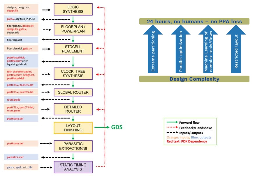
In physical design, various stages of processing refine the abstract logical design, as represented by the gate-level netlist, into the final geometric layout of the GDSII file that is needed for foundry fabrication. The GDSII file contains a database of geometrical design information consisting of many layers of geometrically defined objects that are used to create the pattern masks needed for IC fabrication.
The design flow uses various tools and files during the stages of processing to optimise the placement of items in the netlists and the routing of interconnections between them without breaking any of the design or manufacturing constraints.
Although viewed as a sequence of stages of refinement from abstract logical design to final layout, the activity is usually as number of iterations of the Physical Design processes, each optimising the physical design towards certain design goals based on power, performance, area, etc.
The major Electronic Design Automation tool vendors have various tools to support the Physical Design flow stages. The OpenROAD project is developing a fully autonomous, open-source tool chain for digital layout generation with an initial focus on the RTL-to-GDSII phase of system-on-chip design. The aim is to implement automated flows using integration of machine learning, problem partitioning and decomposition, and parallel/distributed search and optimization.
Tool chains support varies proprietary or open file formats for intermediate results.
- Cadence
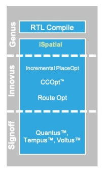 The Cadence physical design flow follows from Genus (synthesis) through Innovus (place and route), Tempus (static timing), and Voltus (IR analysis) which all operate off a single data model to ensure overall design integrity as various aspects of the physical limitations associated with actual fabrication using a specific foundry technology are factored into the final design to be sent to the foundry.
 Die Area / Floorplan Aspect Ratio
The Cadence tools offer an Automatic floor plan option to get an early view of area which can be helpful in higher level design decision making. In SoC Labs projects this tends to be used to get an initial area view for a custom accelerator design, especially if the RTL design has been generated.
Power
The Cadence Voltus tool provides power analysis, especially IR drop.
- Synopsys
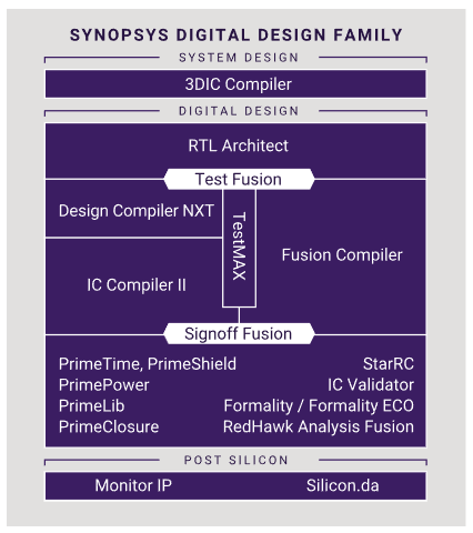 The Synopsys physical design flow follows from Fusion Compiler (synthesis) through sign off tools.
 Die Area / Floorplan Aspect Ratio
The Synopsys tools offer an Automatic floor plan option to get an early view of area which can be helpful in higher level design decision making. In SoC Labs projects have used RTL Architect to get an initial area view for a custom accelerator design, especially if the RTL design has been generated.
Timing
Clock tree synthesis is undertaken within the IC Compiler II tool. The PrimeTime tool with IC Compiler II provides capability to check all possible paths for timing violations.
Power
The PrimePower tool provides power analysis, especially IR drop.
Explore This Design Flow
Projects Using This Design Flow

Experts and Interested People
Members


Related Project Milestones
| Project | Name | Target Date | Completed Date | Description |
|---|---|---|---|---|
| Battery Management System-on-chip (BMSoC) for large scale battery energy storage | Physical Design |
Digital Design
|
||
| Interference Detection and Mitigation Accelerator for Automotive Radar SoCs | Physical Design (93) |
Developing ASIC (65 nm) flow and integration possibility of accelerator with nanosoc |
||
| ADC Integration in nanoSoC | Physical Design (93) |
Physical design of ADC |
||
| Aspen: A 630 FPS Real-Time Posit-Based Unified Accelerator for Extended Reality Perception Workloads | Physical Design (93) |
Comments
Other resource for physical design
Here is a good resource for getting started with physical design using the cadence innovus tool. It takes you through step by step from a netlist file to gdsII export.
Add new comment
To post a comment on this article, please log in to your account. New users can create an account.